|
Instructions
Ver. 1.3 - updated to July 12, 2016 |
|
DISCLAIMER I’m maker, not a professional translator. English is not my mother tongue. - please be understanding - |
| Introduction |
|
LŪCIBUS was tested with following inverters : MPP SOLAR 4848 - MS e MSX
and it is compatible with following MAIN firmware : 32.40 - 52.25 - 52.3 - 52. 4 - 72.4 - 72.5 - 75.0 - 75.1
This inverter seems to compatible with following "twin" devices : (same hardware and firmware but different factory label). ADVANCE KS GENIUS KVA TECNOWARE ATA AXPERT MKS GIANT POWER 48 FLINSLIM KVA SP EFECTO SP BRILIANT
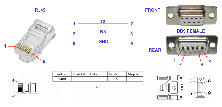
This is the RS232 wiring diagram to connect the inverter to the pc serial port. Usually this cable is equipped with the inverter.
WARNING : AT MOMENT LUCIBUS DOES NOT WORK WITH USB. ONLY SERIAL PORT IS ALLOWED If your pc has not a serial port, you need to buy an adaptor. I tried a lot of adaptor and the this is best. It works with WIN10 too :
ABC Products® USB a 9 Pin DB9 Serial
click HERE for Amazon italian link
This adaptor has a cheap price and remove big problem about drivers and program freeze I have two of these and are working fine from march of 2016 |

|
MAIN PAGE |

|
1. Communication port. For number choice and autostart go to SETUP paragraph. If com port communicates
with inverter, the colour will change from green to red. The internal number
indicates the serial number. 2. 3. Recording light. Every 15 minutes is red blinking for a minute. It indicates that ram data are recording (for graph production and consumption). If clicked, allows recording data out of expected time. 4. Command sent to inverter. 5. If clicked, allows to hide the Tx-Rx strings from-to inverter. 6. Voltage and capacity of batteries. The small number on top-right indicates - theoretically - voltage of single battery. To obtain this number, needs to configure number of elements that compose 48 volts. SETUP menu will help to do it. 7. Surplus ampere and watt. If number is green, it means that there is a surplus of production. If number is red, it means that would need more X watt to reach the current needs. 8. Type of charge of battery (solar - none - line). The below balance is red if actual charging is bulk, green if float. 9. Max volt-watt daily peak of panels production, and own time. It's reset at the sunrise of day after. 10. Volt-watt of regulators, with adding of ampere and on time production. Figure shown 3 regulators model. Model with only one regulator blinds num. 2 and 3. 11. Consumption and % used by the load. 12. Type of power for loads : yellow = solar green = battery red = line. 13. Max daily peak about inverter temperature, and relevant time. It's reset at midnight. 14. TOOL menu. 15. TIMER menu. 16. STATS menu. 17. Enables web pages for data display on remote pc or smartphone. From the top, numbers mean : Pc Ip, used port, views of homepage (left) and graph (right). Configuration may be modified in SETUP menu. 18. Clone view of original display on inverter. 19. ALARM menu. 20. LOG menu, directly to MAIL. Number on left of envelope shown sent mails. It resets at midnight. 21. Inverter answer string after sent command (please look at point 4). 22. HELP menu. 23. Information and credits about LŪCIBUS. 24. Label that shows on web page. Name and colour may be changed in SETUP menu. 25. SETUP menu. 26. LOG menu. Icon may blink, to warn you that there are too errors. Threshold number may be changed in SETUP menu. 27. It allows to iconize MAIN page. |
|
PRODUCTION and
CONSUMPTION - summary view |

|
A. Total Watt of today. B. Total Watt for 15 minutes of current recording.
1. Panels production. 2. Surplus production (power that should be used for other purposes, because is produced but never used from loads). 3. Gran Total about consumption (all included : line - battery - solar) since you started LŪCIBUS 4. Daily general total about consumption (totals of 5. 6. and 7.) 5. Daily general total about LINE consumption 6. Daily general total about 7. Daily general total about SOLAR consumption Point 5. 6. and 7. shown, substantially, what kind of power is used by load. Figure shows 3723 W consumed: 2946 from battery and 783 from solar. No line power was used. 8. Complete view of PRODUCTION AND CONSUMPTION menu. 9. Simulation of RED LED inside LINE counters. Blinking is proportional to watts used from loads, in the same way of official counters. |
|
PRODUCTION and
CONSUMPTION - full view |

|
1. Toggles views in W or kW 2. CALENDAR menu Totals display situation about PRODUCTION and CONSUMPTION. In the example the totals are calculated between may 14 and today 3. Power produced by FV panels. 4. Yeld,that means percent value between stored energy and battery drawn energy . Normal value is 75% or more. If it increase, means that system is well strunctured and battery capacity is appropriate to their own consumption. Month value is credible after 20th day. Please see YELD PEAK graph. 5. Taken watt from sun and batttery to power the load. It means the total free power. It is the sum of 8 and 9. 6. General watt to power the load : this counter is the sum of 7,8 e 9. 7. Taken watt from line power supplier to power the load. If fine-tuning (section 4 of setup) is well configured, this counter is the twin of official counter of line power supplier. 8. Taken watt from battery to power the load. 9. Taken watt form sun to power the load. |
|
PRODUCTION and
CONSUMPTION - CALENDAR - Count of consumption according to personal
date range |

|
This icon enters in choice menu, that allows a personal
count - as needed - of all totals 1. Date range start. 2. Date range end. 3. Previous day automatic display. 4. Previous 7 days automatic display from today. 5. Previous 30 days automatic display from today. |
|
ERRORS log and
recording |

|
Explanations for this menu are not required. By
clicking on options, logs of that section will be shown. By clicking on first column (name column) ascending and descending data will be alternately displayed. In case of slow visualisation, it’s recommended to delete all logs, using the relevant command (top right of form). |
|
TOOL |

|
This menu allows to send direct commands to
inverter. As a reference, you can use the pdf doc located at www.homoandroidus/LŪCIBUS 1. Data copy of field 3 2. Deleting of field 3 3. Blackboard display for Tx-Rx data 4. Ready-to-use commands 5. Window for custom commands sending |
|
TIMER |

|
This is one of more interesting menus.
Practically, LŪCIBUS was engineered for this purpose, then exponentially
grown up but basically its backbone is here : in the timer. The timer menu is made of two different utilities.
A. POP UTILITY Useful when you need that inverter toggles from utility to solar or other options at fixed hours during the day. What is it? Here is my needs (please look at image): From 7 PM to 10.59 PM usually in my home there is high consumption of power due to dinner and after-dinner: oven, dishwasher etc. During these 4 hours, if i had to supply so powerful loads using battery, I'd lost all stored energy during the day and battery would be stressed, even because going toward night and it wouldn’t be charged until next day. Using this utility, I force inverter to use line power. I protect the battery, so that can supply normal load when all family is sleeping. In this way, I'm detached and self from line power until next morning, when sun light will be able to charge the battery and supply load through panels. To pay for 4 hours of line power is better than to buy again battery in a short time.
1. Inverter current situation 2. By clicking on it, will be rotary viewed a different colour that is related to the type of configuration. After you have chosen the colour, click on hour required. 3. Daily timer for configuration change. 4. Flag to enable configuration. Utility will be active only if flag is enabled.
B. PCP UTILITY Useful when you need that battery is charged in fixed hours during the day and/or choosing parameters What is it ? This is typically a winter menu and is useful for user who want to charge battery only in solar mode (almost everyone!). Often, during the winter, cloudy days are many and continuous. For this reason battery is not fully charged like in summer time and may happen that in some days, battery are not fully charged enough. So, using this menu you can force inverter to
charge battery during fixed hours of the day (in Please look at the image: flag is on “THRESHOLD Enabled”, that means you are forcing inverter to charge battery between midnight and 3 AM, but only if battery voltage is below 49. When voltage will reach 50, charge will finish and inverter come back to “solar charge”. If you want to charge anyhow, you must enable “ALWAYS enabled” flag and put required colour in the hour box. If you don’t want charge at all, hours must be in yellow colour. 5. Inverter current situation 6. PCP utility works anyway during red
hours, without considering min-max threshold. 7. PCP utility works during red hours
but considers min-max threshold. In figure example, battery is charged only
if voltage is below 49. Charge will be completed when voltage will be 50.1. 8. By clicking on it, will be rotary
viewed a different colour that is related to type of configuration. After you
have chosen the colour, click on the hour required. 9. Daily timer for configuration
change. 10. Min threshold 11. Max threshold |
|
STATS |
|
This menu allows to display a series
of graphs about production, consumption, battery voltage, inverter
internal temperature and yield. |


|
MONTHLY QMOD graph is very
important because allows to display day-by-day load situation. Each day is
divided into 96 zones of 15 minutes each. |

|
The same graph also allows
to display daily situation by clicking on day number (see blue arrow). A
further graph will be displayed, divided into 1440 minutes, with relevant
consumption peaks and colours related to type of load power. Please see sample below: |

|
Please remember that most of ABOVE GRAPHS are viewable on the web. |
|
SETUP |

|
This menu allows to do
several LŪCIBUS configurations, through submenus too. 1. Allows the automatic
start of program, without clicking START command from main. To obtain this
action is necessary to enable AUTORUN flag. If web start is needed, please
enable WEB flag too. Al last, very important, please choose serial COM port used for communication with inverter. During choice, only available ports among the present ones, will be displayed. 2. If flag is enabled, in
case of missing line power pc speakers will play a mp3 every 20 seconds. Mp3
file is located within WEBPAGE folder. 3. If flag is enabled,
allows to save main page position on monitor. If you move page, after 20
seconds it is saved in new position, so that when you restart LŪCIBUS, main
page will be positioned in the same place. 4. This is a very
important function: it allows to increase or decrease a number needed
for approximate count of consumption. Inverter works at 2400 baud, so it is very slow. It is possible
to catch a valid data number every 3 or 4 seconds, without errors. It means
that is impossible to calculate an accurate count. So we need to use an
average count, that is subjected to many variables: cpu
speed, communication quality, random errors etc. These problems may be solved
using a variable chosen by user. It allows to adjust delays or excessive
speed during count. We
experienced, after many tests performed on several inverters in User will perform some tests to find his correct number,
comparing the total of line counter with LŪCIBUS
counter. A daily reading may help to increase or decrease. In a week you
should be able to obtain an acceptable result. 5. Allows to change bars
colour of internal graph (not active, at moment, for web graphs) 6. If case of exit before
data saving (that occurs every 15 minutes), this option allows to save all
variables still in ram, so that no data will be lost. 7. PARAMETERS submenu 8. E-MAIL submenu 9. By setting the number
of batteries composing 48 volts, the THEORETICAL voltage of each element will
be displayed on main, located on the upper right corner of the battery
voltage view. 10. Sets the number of red
icon with exclamation point in main page (see point 26) beyond which the icon will begin to
blink. It needs to display a warning about a too high number of errors. It’s
necessary to display a warning when the number of errors becomes too high. 11. Defines name and
colour of label on To test the web page on local pc, open browser and digit: http://localhost:8090
(or choosen
port) To test the web page on internet (browser or smartphone),
it’s required to set PORT REDIRECTION from NAT
(Network Address Translation)
menu of your router. 12. Available languages |
|
PARAMETERS |

|
This menu is still under construction
and allows – at the moment – to display the inverter essential configuration.
I hope to create as soon as possible a version that will allow to write data,
so you that you no longer need of WATCHPOWER to set inverter. Watchpower is a very good utility, but is not comfortable to use two different programs for the same inverter. |
|
E-MAIL |

|
This menu allows to set the configuration
of mail server that will send alarm and warning messages. Insert
necessary data and enable flags you need to be advised by e-mail.
Number of daily mail (that resets on
midnight) is displayed in main menu, on the left of envelope (SITUATION
FORM). To check how many and which mail were sent, click on envelope
(see point 20 of main). WARNING: GMAIL users must
enable mail sending from no-google server. This
option is located within your google account. |
|
FAULTS and ALARMS |

|
If a fault or alarm is occurs, bell
triangular icon blinks (main - point 19) . By clicking on this icon, this menu
will be displayed, with coloured icon of detected fault. In the example,
inverter produced a “blocked fan” error. By clicking on fault icon, error log
will be displayed. If e-mail warning is enabled, a
message will be sent to configured mail box to report this fault. To test all icons, click on ICON TEST. All icons will be turned on, as in sample below . |

|
HELP |

|
A little help is also available. You can choose internal or external help. Usually external help (on web) is more updated and complete than internal. |
|
THANK YOU FOR HAVING HAD THE PATIENCE TO READ IT ALL !!! |

|
Copyright 2016 HomoAndroidus Webdesign Fotosettore - Marchio Registrato
2003 |